Overview
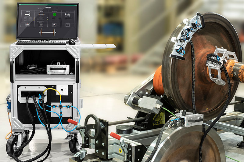
Phased Array Semi-Automated Wheelset Inspection System (PASAWIS)An application-tailored, all-in-one solution, our Phased Array Semi-Automated Wheelset Inspection System (PASAWIS) improves the ease, efficiency, and reliability of maintenance inspections of wheelsets with solid axles. |
|---|
Complete PA Inspection SolutionPASAWIS uses a combination of the latest ultrasonic and phased array scanning technology and dedicated application software to achieve complete coverage of wheelset components. Increasing inspection speed and reliability, multiple phased array probes electronically scan the targeted area while a dedicated scanner maintains optimal positioning on the component. Exploiting the electronic scanning capacity of phased array probes provides significant improvements in efficiency and coverage compared to the manual scanning of conventional UT. The PASAWIS software is tailored for the application, making it much easier to use than typical ultrasonic or phased array inspection devices. |
|
Full Coverage of the Axle, Rim, and TreadPASAWIS can be configured with up to three handheld scanners, each optimized for a different wheelset component: axle, rim, and tread. These dedicated PAUT scanners are designed to fit flush with the component to accelerate inspections through comprehensive coverage, reliably detecting all relevant indications. 4x Faster Inspection SpeedsPerform complete inspection 4x faster with the PASAWIS system compared to conventional UT inspection. Programmed with industry requirements in mind, the acquisition software helps ensure that the mandatory steps of the strictest standards are performed quickly and efficiently. Maximum Effectiveness with Minimal TrainingThe software user interface provides a complete guided workflow that optimizes the inspection steps, achieving the effectiveness of an automated system with a semi-automated solution. Thoughtfully designed for wheelset inspection needs, the PASAWIS system is easier to operate than a typical flaw detector. Consistent, Reliable ResultsControl the human impact on data collection and inspection results through this solution’s step-by-step workflow, guiding operators through the entire procedure. With its 2-level access, PASAWIS provides operators with the necessary access to the inspection workflow while making sure the supervisor’s requirements are met. This is key to achieving reliable results that are independent of the operator performing the inspection. |
Key Advantages of the Phased Array Semi-Automated Wheelset Inspection System
|
 |
Dedicated Scanners |
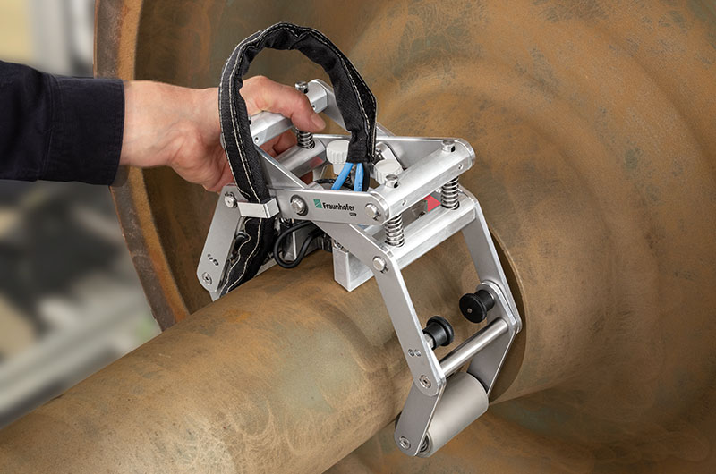
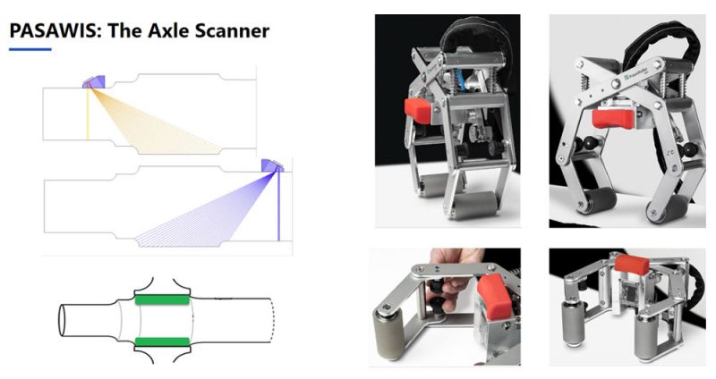
| Axle ScannerThe Axle Scanner is dedicated to solid axle inspections from the shaft and journal positions (typically at the dismounted stage). Using phased array probes, the system inspects the full wheel seat area from both sides, providing automatic transfer correction, a coupling check, and missing data points control to help ensure high-quality data acquisition. |
|---|
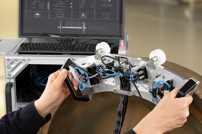
Wheel Rim ScannerThe wheel rim inspection is performed simultaneously in two directions. It uses two phased array probes for the rim area and two conventional UT transducers for the flange area. In a single pass, it enables a complete inspection of the rim, offering an automatic coupling check and missing data points control. |
|
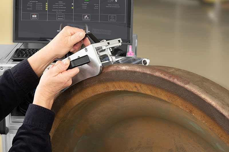
| Wheel Tread ScannerThis unique phased array solution for wheel tread inspection provides required reference defects detection in all areas (defined in VPI-EMG 09). Applied directly on wheel tread, the scanner inspects the full width in one pass. |
|---|
Software
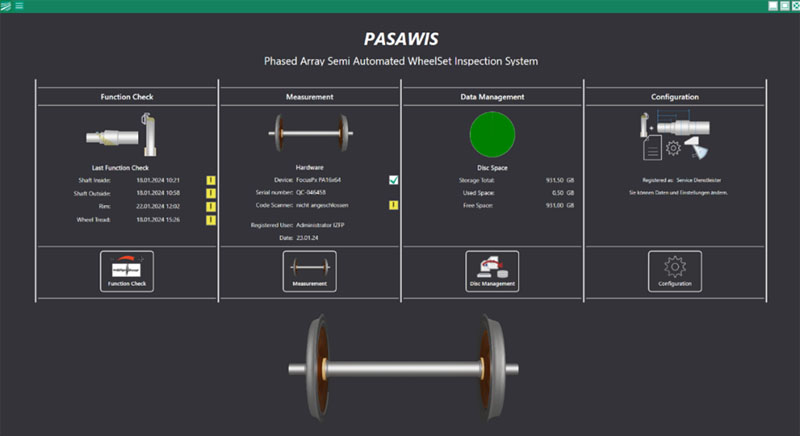
PASAWIS Acquisition and Data Analysis SoftwareOur dedicated PASAWIS software provides several predefined inspection workflows, optimized for each wheelset component. The software guides the user through all the inspection steps, helping ensure full compliance with your inspection procedure requirements. The software interface is displayed on a large touchscreen monitor that provides clear visualization of the wheelset components and testing data. When the inspection is complete, inspection reports are generated in PDF format with minimal input required from the operator. Report contents:
|
Function CheckVerification of NDT device settings and sensitivity is key to performing a proper inspection. With automated or semi-automated solutions, this function check is even more critical due to the mechanics and coupling involved. PASAWIS inspection software has a built-in safeguard that not only advises you when the last function check was performed, but also prevents you from performing measurements if the function check is overdue. A supervisor can be assigned ownership of the inspection procedure to establish the function check schedule. | 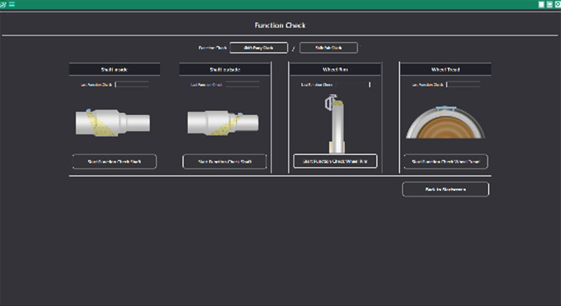 |
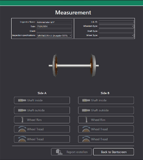 | MeasurementsThe Measurement screen includes all wheelset data and the components that needs to be inspected. Completed inspections are indicated with green checkmark for easy identification. You can create a report at any time, and the software will notify you if any components were missed. |
|---|
Software Features:
|
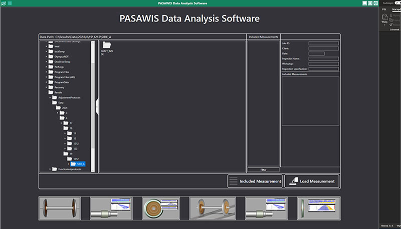
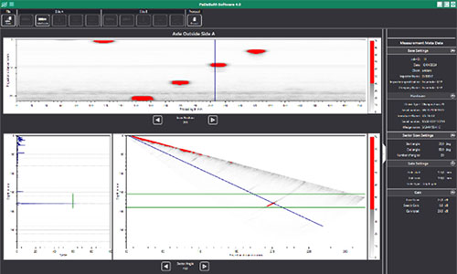
Data Analysis Software for Post-Inspection ReviewDelivered with system, PASAWIS data analysis software enables you to review all the recorded data and perform the analysis at any time after the inspection is complete.
|
 |  |
Specifications
System Specifications
| Phased array channels | 64 |
|---|---|
| Number of pulsers | 16 |
| Conventional UT channels | 4 (8 UT connectors) |
| Data acquisition rate | Up to 30 MB/s |
| Acquisition speed | Up to 20000 12-bit A-scans/second of 750 points each |
| Amplitude resolution | 8 bit / 12 bit |
| Maximum number of A-scan samples | 16380 |
| Real-time data compression | 1 to 2000 ratio |
| Rectification | FW, HW+, HW–, and RF |
| Filtering | Digital band-pass, high-pass, and low-pass filters |
| Voltage | PA: 4 V, 9 V, 20 V, 40 V, 80 V, and 115 V UT: 50 V, 100 V, and 190 V |
| Gain | PA: 80 dB; UT: 120 dB |
| Pulse width | PA: 30 ns to 500 ns (steps of 2.5 ns) UT: 30 ns to 1000 ns (steps of 2.5 ns) |
| Bandwidth (−3 dB) | PA: 0.6 MHz to 17.8 MHz UT: 0.25 MHz to 28 MHz |
| Number of beams | Up to 1024 |
|
Pulse repetition
frequency (PRF) | Up to 20 kHz |
| Real-time averaging | PA: 2, 4, 8, 16 UT: 2, 4, 8, 16, 32, 64 |
| Encoder | 2 axes (quadrature, clock direction) |
| Network interface | 1000BASE-T |
| IP rating | IP 65 |
Base Unit Specifications
- Dimensions: 1195 mm × 615 mm × 605 mm
- Weight: 110 kg
- Wheels: diameter: 200 mm, width: 65 mm made of rubber
- Water management system and scanner encoder switch
- Data storage: 512 GB SSD + 1 TB SSD
- Monitor: 24-inch. touch screen monitor
- Installed software: single user license for inspection software and single user license for offline analysis software
Axle Scanner Specifications
- Dedicated to solid axles with diameters of 130 mm–180 mm with the standard wedge (for bigger diameters, an additional wedge is needed)
- Phased array inspection of axle wheel seat area from journal and shaft position with automatic coupling check function
- Integrated encoder and coupling system
- Latch mechanism with diameter adaptation
- Includes phased array probe, wedge, two spacers, and a transport case
Wheel Rim Scanner Specifications
- Dedicated to wheel rims of wheels with diameters of 750 mm–1000 mm
- Phased array inspections of the wheel rim and conventional UT inspection of the wheel flange (two directions at the same time) with automatic coupling check
- Integrated encoder and coupling system
- Magnetic mechanism for scanner attachment and spring-loaded probe holders
- Includes two phased array probes with wedges, two conventional transducers, and a transport case
Wheel Tread Scanner Specifications
- Dedicated to wheel treads of wheels with diameters of 600 mm–1000 mm
- Phased array inspection of wheel tread area (rolling surface), with visual coupling check
- Integrated encoder and coupling system
- Spring-loaded probe holder
- Includes phased array probe, wedge, and a transport case
