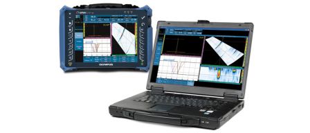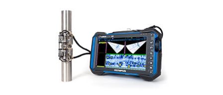
The COBRA scanner and OmniScan MX2 flaw detector used for inspection of heat exchanger coils during manufacturing
Introduction
Inspecting heat exchanger welds is challenging because of the number of welds to inspect and their close proximity. To be able to reach the welds and to achieve high productivity, it is important to use a tool that is optimized for this type of inspection. Olympus’ COBRA® scanner can be used to inspect diameters ranging from 0.84 in. OD up to 4.5 in. OD. It accommodates up to two phased array probes in limited clearance situations. This application note presents a case shared by a customer who successfully used the COBRA solution with an OmniScan® flaw detector to perform phased array ultrasonic testing in lieu of radiography.
Why Phased Array Ultrasonic Testing Was Chosen over Radiography
Dreifeld Materialprüftechnik GmbH is German inspection company that was tasked with inspecting heat exchanger coils in a manufacturing plant. The parts, which are composed of multiple pipes and bends, are used for air-to-fluid heat transfer in the power generation industry.
Although radiolographic testing (RT) was the primary NDT method suggested by the manufacturer, Dreifeld concluded that ultrasound testing (UT) would be a more advantageous method.
Multiple reasons led to this decision. First, RT inspection would have required twice as many inspectors and, since implementing a safety zone was deemed too difficult, it would have needed to be performed during the night while the other employees were away. It was estimated that the complete project using RT would take five times longer than UT, and with the pay rate being higher during night shifts, it would be costly in terms of labor. This is on top of all the extra costs associated with RT, including consumables such as film, photo chemicals, and waste disposal of the lead foils. Another important aspect of choosing UT over RT is related to the probability of detection. For example, lack of side wall fusion, which is a critical flaw to measure, is not well detected by radiography.
Solution Using the COBRA Scanner and Phased Array (PA) Technology
The outside diameter of the heat exchanger tubes was 76 mm (3 in.) with a wall thickness of 4.5 mm. A custom block was designed and manufactured to calibrate the wedge delay, angle sensitivity, and time-corrected gain (TCG). The welds had 30° V-shaped bevels and were located between a section of pipe and an elbow. Because the COBRA scanner cannot be used on the elbow side of the weld, it had to be setup in a one-sided configuration. This is easily achieved by removing one side of the COBRA scanner and only using the side with the encoder. A manual water pump was used to provide couplant for the wedge. | 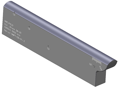 Fig 2: The custom calibration block |
 Fig 3: The COBRA scanner configured for one-sided inspection | Dreifeld used an OmniScan® MX2 16:128 phased array ultrasonic testing (PAUT) flaw detector, in which two different groups were created. The first group was a shear-wave sectorial scan setup to do 50° to 72° sweep with an angle resolution of 0.5°. The second group was an L-wave 0-degree focal law used to check the couplant. The scan resolution was set to 1 mm and the beam was generated with a 16-element aperture. A total of 1604 welds were inspected in eight days, with a daily maximum of 320 welds. The entire inspection was done with only one inspector and one set of equipment. A typical shift involved eight hours of scanning and two hours of data analysis per day. |
Automatic Data Processing Helps Accelerate Analysis
The data files were processed through Automated Detection Technology™ (ADT) software by VeriPhase® for automatic analysis. A major advantage of ADT software is that it can be loaded with multiple files (between 100 and 300, in this case), and the software generates an Excel® report showing previews of all indications. The ADT report also marks any data quality issues to help ensure code compliance. A table of indications is then populated by the software directly into the OmniScan data file for final disposition in OmniPC™ data analysis software. All relevant flaw positioning and sizing information is included. Indications can be easily reviewed straight down the weld by clicking the indications. Any necessary display changes are automatically made, and reference, as well as measurements cursors, are positioned in their applicable height and length positions for each flaw. Indications can easily be updated or deleted for the final report.
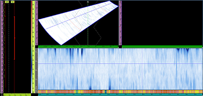 Fig 4: Multigroup A-C-S view of a weld without defects with the couplant check group displayed at the bottom | 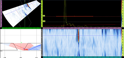 Fig 5: A-C-R-S view of a weld with a lack of side wall fusion detected on the second leg (probe side wall) |
 Fig 6: A-C-R-S view of a weld with a lack of side wall fusion detected on the third leg (far side wall) |
Detection of defects on the far side fusion wall is possible if the weld cap is regular enough to allow sound to be reflected without too much diffraction. This was the case in this application. The extra travel distance caused by the crown height makes the defect appear a little further from and not directly on the weld bevel, but detection was found to be very good. |
Conclusions
The Olympus PAUT solution composed of the COBRA scanner, the OmniScan MX2 flaw detector, and ADT software from VeriPhase was used to fully inspect and analyze 1604 heat-exchanger tube welds in eight days. Only one inspector was required to operate the equipment and perform the analysis. Using a phased array solution instead of radiography helped prevent missed indications, such as lack of side wall fusion, and avoided complications related to safety. It was estimated that the project was performed five times faster than using RT and at a fraction of the cost.

