Videoscopes have moved far beyond basic imaging. Today, modern high-end industrial videoscopes offer advanced features that can bring greater precision and reliability to aircraft gas turbine inspections.
Here, learn about two modern videoscope capabilities that help give aerospace inspectors more confidence in their measurement results.
1. Stereo Measurement
The first advanced videoscope function that provides precise imaging data for aviation inspections is stereo measurement.
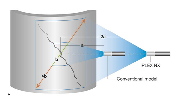
Paired with the right optics, stereo measurement enables the user to quantify defects in 3D space regardless of the tip-to-target angle and type of defect. In addition, stereo measurement on the IPLEX™ NX videoscope delivers a 4x larger field of view and a more extended depth of field compared to conventional models.
So, how does this benefit inspectors? Stereo measurement helps in three main ways:
Get a higher probability of detection: An expanded field of view and depth of field mean you can see and measure defects from farther away compared to conventional scopes, giving you a higher probability of detection. After all, you can’t measure what you can’t see.
Measure with precision: Modern videoscopes also use smart techniques to improve stereo measurement accuracy. Our IPLEX NX videoscope, for example, uses one-to-one matching between the scope unit and the stereo tip adaptor, enabling the measurement algorithm to reduce the error range that occurs as the tip-to-target distance increases. The optimized optics and image sensor also help you select the best measurement point for repeatable results.
Finish inspections faster: To inspect faster is to inspect once and obtain the most reliable result. The quality of stereo measurement results depend on the optimal tip-to-target distance, and modern videoscopes such as the IPLEX NX can provide real-time tip-to-target distance in 3D space before the inspector even starts to perform a measurement. This IPLEX NX function, called Multi Spot-Ranging, enables faster and more confident measurement results.

Expanded measurement capabilities on our IPLEX NX industrial videoscope (a) enable detailed measurements from greater distances (b).
Multi Spot-Ranging |
2. 3D Modeling
Even with advanced stereo measurement capabilities, accurate and precise measurements still depend on how precisely you set reference points and measurement points. Setting these parameters can be challenging in certain situations, such as measuring parts with complex scenes, difficult lighting conditions, and irregular surfaces.
So, how do modern videoscopes enable precision in point selection? The answer is 3D modeling.
For instance, the 3D modeling feature on our IPLEX NX videoscope makes it easier to visualize the precise shape of critical components. It gives you an enhanced knowledge of the target with various 3D views in addition to the standard 2D stereo images. Other benefits of 3D modeling include:
Powerful renderings: The Reference Plane rendering, for example, enables you to quickly understand protrusions and depressions with distance values and color-coded 3D models.
Real-time 2D and 3D connection: Pixel selection updates in real-time between the standard 2D stereo view and the 3D modeling view. This helps inspectors visually confirm the selected pixel is where it should be in the 3D space to reduce the risk of misplaced measurement points and the need to remeasure.
Virtual slicing of 3D models: With this function, you can easily remove unnecessary sections from the 3D model to focus on the crucial areas.
Now that you have an understanding of stereo measurement and 3D modeling, we will share how these advanced remote visual inspection features benefit inspectors in practice. Keep reading to explore an aviation case study.
Case Study: Measuring Tip Gap Clearance Using Modern Videoscopes
Conducting a tip gap clearance measurement is a challenging but important aviation inspection task. It requires the correct placement of reference points, and the result could lead to critical conclusions that affect engine efficiency or even safety.
For those who are unfamiliar, a tip gap clearance measurement looks at the distance between the blade tip (for example in a high-pressure compressor stage) and the engine shroud.
In gas turbines, the clearance between the blade tip and the shroud is essential for engine performance. Without adequate clearance, the blades can become damaged. Too large of a clearance will lead to decreased compression and reduced engine efficiency.
For these reasons, it’s essential the tip gap clearance remains within specification throughout the engine’s service life.
The Challenges of Measuring a Tip Gap Clearance Using Conventional Videoscopes
But measuring tip gap clearances with a conventional videoscope can be tricky.
Here’s why: Enlarging the inspection area means moving further away from the target object within the lens’ depth of field. Yet, the furthest distance away from the target for a conventional scope is often around 20 mm (0.8 in.). Beyond this distance, the accuracy drops significantly. In some cases, measurement is impossible.
So, how do you get accurate and precise measurements?
There are two factors to consider when measuring any critical part using a videoscope: the size of the object to be measured and the distance from the object. These key factors can affect measurement accuracy, so you must know how far away the scope tip is from the object before measuring.
The Benefits of Measuring a Tip Gap Clearance Using Modern Videoscopes
To address this issue, modern videoscopes can determine the tip-to-target distance (or Z-distance) on the live image before measurement begins.
By measuring the Z-distances of all pixels within the stereo image, the videoscope can present samples of these distances in real time while highlighting as many as five individual Z-values in any region of the stereo image. This helps you understand the surface profile and get important details to measure confidently.
This feature greatly assists tip gap clearance measurements, since the angle between the videoscope and the tip gap can cause an incorrect perception of the clearance boundaries. For this reason, a tip gap clearance measurement is taken as a depth or height gap measurement. To conduct this measurement, you must set a reference plane at a known surface and take measurements perpendicular to this plane.

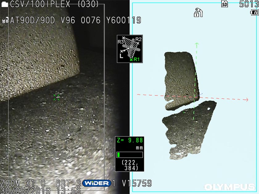
2D stereo image and 3D model of the gap between a blade tip and engine shroud.
To see what this looks like in practice, check out the image above. It shows a 2D stereo image and 3D model of a compressor blade close to an engine shroud. The image was captured using our IPLEX NX industrial videoscope, which can carry out accurate measurements with tip-to-target distances up to 60 mm (2.4 in.).
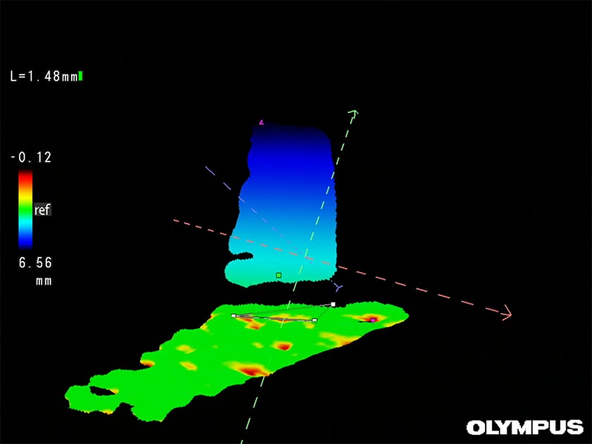
Here, a reference plane is defined on the flat surface of the shroud. You can quickly check the correct orientation of the plane by switching to 3D mode. For more visual clarity, you can add color coding as shown in the image below.

Color coding in a 3D model indicates if points on a surface lie below or above a defined reference plane triangle. Green: in the reference plane. Red: below. Blue: above.
Once you are confident the plane is correctly defined, measuring the tip gap clearance is easy to do. In the image above, the selected pixel measures 1.48 mm from the reference plane defined by the triangle.
Modern Videoscopes Provide Confidence for the Future of Flight
Aerospace inspections are essential for safe and efficient air travel. Precise RVI measurement capabilities like stereo measurement with 3D modeling can give you the confidence to perform aviation inspections today and in the future.
Related Content
Application Note: Visual Inspections of Commercial Jet Engines
Brochure: IPLEX NX Industrial Videoscopes
Get In Touch

