Are Your Laser Confocal Microscope Measurements Trustworthy? Self-Verify Using the 9-Point Measurement Test
Scanning laser confocal microscopy (SLCM) has become a popular inspection tool in both research laboratories and manufacturing production lines. With a 405 nm laser light source, SLCM combines high-resolution horizontal (XY ~200 nm) and vertical (Z ~10 nm) information to create a three-dimensional (3D) image within seconds. SLCM’s measurement scale overlaps with optical light microscopy (OLM), scanning electron microscopy (SEM), and atomic force microscopy (AFM). In addition, there are minimal sample preparation requirements, and the microscopes can accommodate samples with a wide range of shapes, including large sizes. No consumables are required with SLCM, and there’s minimum system maintenance. All these benefits make SLCM a useful inspection tool. The table below summarizes the difference between these four techniques.
Comparing Scanning Laser Confocal, Scanning Electron, Atomic Force, and Optical Light Microscopy
| SLCM | SEM | AFM | OLM | |
|---|---|---|---|---|
| Sample preparation | No | Yes | Yes | No |
| 3D image | Yes | No | Yes | No |
| Consumables | No | No | Yes | No |
| XY resolution | ~100 nm | 10 nm | 0.1 nm | ~300 nm |
| Z resolution | ~10 nm | NA | 0.1 nm | NA |
| Vacuum | No | Yes | No | No |
| Imaging speed | Fast | Fast | Slow | Fast |
As a high-resolution metrology technique, SLCM features high accuracy and repeatability throughout the entire field of view. One way to confirm the accuracy and repeatability of your system is to obtain a calibration certificate regularly, usually once a year. Normally, this would require you to bring out an A2LA-certified service engineer to test the instrument using a NIST-traceable calibration standard. However, there’s an easy way for you to verify your system’s condition on a weekly or monthly basis—a simple 9-point measurement test (Figure 1).

Figure 1. Measure a feature at 9 points in your field of view to help ensure reliable measurements. The blue dots show the position of each measurement.
The method is simple. First, choose an easily recognizable feature or a known sample. Measure the feature at 9 different locations within your field of view, as illustrated in Figure 1. Record the data and perform the measurements again at the exact same locations. If the system’s spherical distortion is well-calibrated throughout the field of view, all data should stay consistent with little variation.
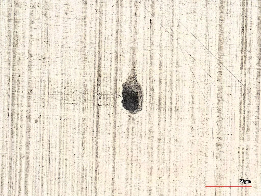
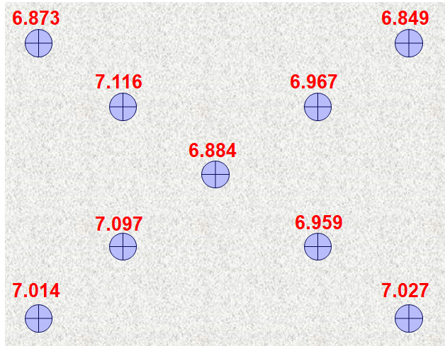
Here’s an example using our LEXT™ OLS5000 scanning laser confocal microscope. We used a steel plate that had a pit on it (Figure 2a), but we recommend that you use a standard calibration sample, if possible. We measured the depth of the pit at the deepest position (Figure 2b). We then moved the pit to 9 different locations within the microscope’s field of view and made the same measurement at each. The average depth was 6.976 µm, and the difference between the minimum and maximum depth was 0.267 µm. The standard deviation was 9.6%, showing that the system was providing accurate, reproducible measurements.
 (a) | 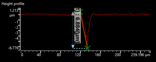 (b) |
Figure 2. (a) The pit on a steel sample and (b) a graph showing the measurement between the highest point on the edge and the deepest point in the pit.
To demonstrate the importance of using the right optics, we swapped out the measurement-dedicated 50X LEXT objective that comes with the OLS5000 microscope with a non-Olympus, off-the-shelf objective. The measurement variance jumped from 0.267 µm to 0.911 µm, and the standard deviation went all the way up to 34.7%! Such a significant variation in the measurement results of the same feature demonstrates that the off-the-shelf objective yielded unreliable data. These results would be unacceptable for most metrology labs and demonstrate the importance of this quick test to help ensure your system’s performance.
 (a) | 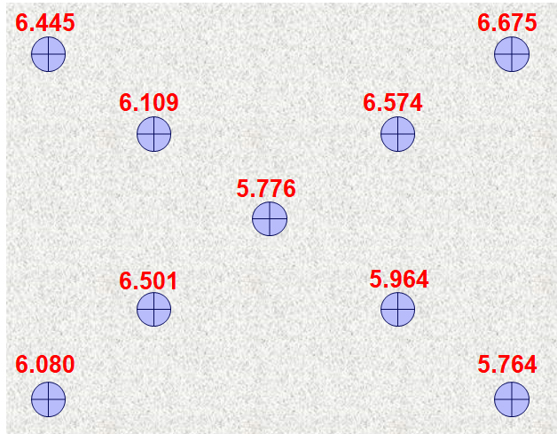 (b) |
Figure 3. The height data (a) using an Olympus LEXT dedicated objective (b) and a non-Olympus, general-purpose, off-the-shelf objective.
In metrology applications for research and manufacturing, measurement accuracy and repeatability are critical. While it’s prudent to have your system professionally validated once a year, this isn’t practical on a weekly or monthly basis. Fortunately, the 9-point measurement technique demonstrated here is a quick and easy way to confirm that your system is still delivering consistent information. It could be useful to add this as part of your standard procedure for system self-verification to help prevent significant variations in data. Further, this test also demonstrates the importance of choosing the highest quality objectives possible to use with your laser confocal scanning microscope.
Related Content
Going Ballistic: Laser Scanning Confocal Microscopy Helps Identify Breech Face Markings
White Paper: The Basic Principles of Laser Scanning Microscopes
Height Measurement of Microscopic Bumps on an Integrated Circuit
Get In Touch
