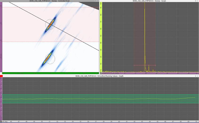
Above is a typical wedge delay calibration using a standard with side-drilled holes (SDHs). You’re probably familiar with images like this, where the SDH’s center is positioned at 0 m. Although this may look nice and compliant, let’s break it down and examine the basic principles. I’ll explain why this is actually bad practice and how it degrades your beam delay accuracy.
Side-Drilled Hole Calibration: Not as Straightforward as You Might Think
An SDH is a good ultrasonic reflector for a specific reason. Regardless of the generated beam’s angle, the round reflector returns the signal to the probe. This is why a radius in an IIW type reference block is chosen to measure the depth for accurate velocity, etc. However, the red zone that we see on the sectorial data display does not represent the actual center of the SDH. More accurately, it’s where the sound first hits the SDH's curved wall.

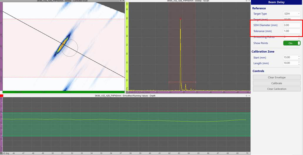
The wedge delay calibration on the left may look good, but it incorrectly bases the beam TOF on the center of the SDH, whereas WeldSight software’s correction calculator accounts for the SDH’s diameter (right) and curvature, so the beam delay calibration is more accurate.
Corrected SDH Calculation Improves the Beam Delay Precision
The Beam Delay calibrator in WeldSight software helps mitigate this inaccuracy. It features an automated correction algorithm to account for side-drilled holes’ diameters. It corrects at different angles along the curvature, as opposed to using the center depth of the hole as mentioned earlier.
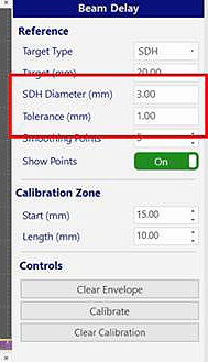
As you can see in the Beam Delay form below, the tolerance remains compliant at 1 mm, but the diameter of the SDH is also entered (3 mm). The software uses this value to calculate the offset between the center of the SDH and where the TOF for the real beam intersects the radius. Notice that the tolerance zone (the green zone in the bottom data display) reflects the offset to include the size of the SDH, but the 1 mm tolerance is not exceeded. Using this method means that the TOF for the beam delay calculations are even more precise than with the typical SDH calibration method.


The SDH’s diameter (3 mm) is entered into the Beam Delay form so the reflection position is accurately calculated and the tolerance zone (the green zone in the bottom data display) still complies with the 1 mm standard
WeldSight software does all the math for you, so it’s an easy way to improve the accuracy of your wedge delay calibration and increase the reliability of your results.
Related Content
Video: WeldSight™ Software for the OmniScan™ X3 Flaw Detector
Video: Olympus around the Word—Wedge Delay Calibration on the OmniScan™ X3
Blog post: Which Phased Array Probe Is Right for Your Total Focusing Method Inspection?

