4.4 一般双晶探头的设置程序
Dual element transducers, incorporating separate transmitting and receiving elements, are commonly used in corrosion survey applications, for porosity detection in castings, and in tests involving rough surfaces or high temperatures. The general procedure for dual element transducer calibration is basically the same as that for contact transducers, the two-step calibration found in section 4.2, with the following additional notes.
1. Remember to set the flaw detector’s pulser to “dual” mode when working with dual element transducers.
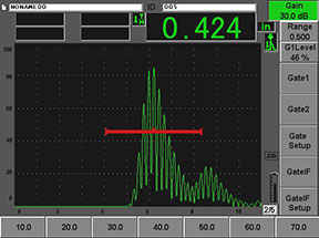
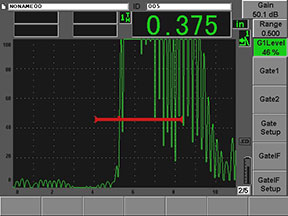
2. When using dual element transducers for thickness measurement, the gain is generally set very high so that the leading edge of the backwall echoes appear as nearly vertical lines on the screen. This is because of the multi-cycle echoes that duals produce. Gates should be set to read to the leading edge rather than the echo peak.
 |  |
| Peak measurement, may be unreliable. | Leading edge measurement, recommended. |
3. Because of the v-shaped sound path that is characteristic of duals, and the lack of v-path correction software in typical flaw detectors, there is some non-linearity in thickness measurements of thin materials. The degree to which this occurs in a particular setup can be determined by checking reference blocks of various thicknesses.
4. The zero offset value for dual element transducers will increase as the transducer heats up. If the temperature of the test piece is significantly hotter than the calibration temperature, the zero calibration should be redone at the higher working temperature.