- Home
- 5G Device Measurement and Inspection Solutions
- Guaranteed Dimension Measurement Accuracy
Guaranteed Dimension Measurement Accuracy
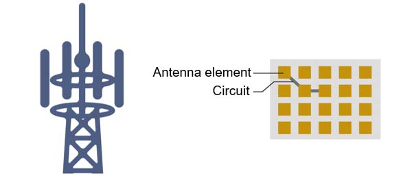
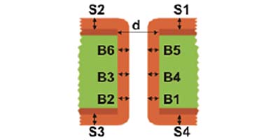
Measuring Base Station Antenna5G antenna have a lot of integrated transmit and receive elements to strengthen radio waves in a specific direction and increase the reception sensitivity. The antenna emits beams from many elements. To keep them from interfering with each other, the elements and circuits must have precise shapes.
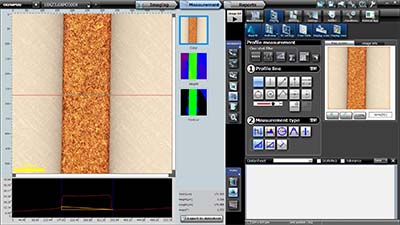
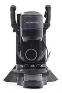
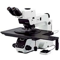
Element Measurement ChallengesA conventional digital microscope may not offer guaranteed measurement accuracy, making the data less reliable. | DSX1000 Guaranteed AccuracyThe DSX1000 digital microscope’s measurement accuracy and repeatability are guaranteed, enabling you to acquire data you can rely on.
Antenna circuit shape measurement
|
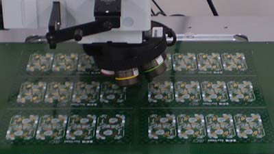
Measuring Printed Circuit Boards (PCBs)5G devices have a lot of components, and they need to be small and thin enough to fit inside modern smartphones. They also need excellent high-frequency characteristics and the ability to withstand a wide temperature and humidity range. To help ensure that PCBs meet these strict requirements, they’re carefully inspected using a microscope.
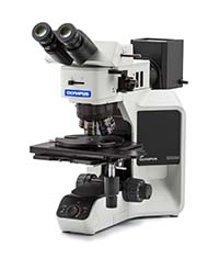
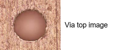
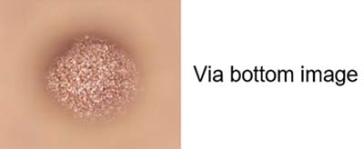
PCB Measurement ChallengesPCBs can be difficult to image because reflectance varies greatly, depending on the material. Without uniform brightness, measurement data may not be reliable. Through-Hole MeasurementThrough-hole measurement is a standard PCB inspection item to make sure the component is manufactured as specified. The through-hole diameter can be easily measured using OLYMPUS Stream™ software’s throwing power measurement and the BX53M or MX63 microscope.
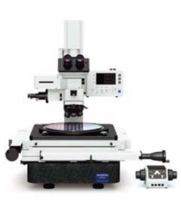
| PCB Pattern MeasurementThe DSX1000 digital microscope and STM7 measuring microscope can both be used to make highly accurate measurements of the width and height of vias and lands in PCBs.
|
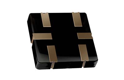
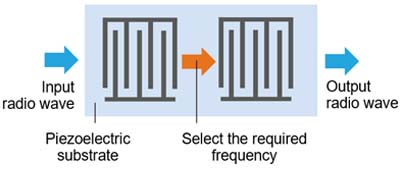
Measuring Noise Filters5G technology uses miniaturized noise filters whose electrodes are extremely small. Because of their small size, measuring the electrode’s size and shape requires advanced inspection equipment.
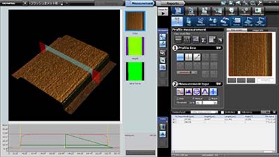
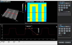
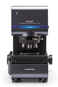
Noise Filter Electrode Measurement ChallengesMetallurgical or digital microscopes may not be able to reliably measure these electrodes due to their small size. | Accurate Electrode MeasurementsThe OLS5100 measuring laser microscope provides highly accurate measurements of fine electrodes with guaranteed accuracy and repeatability.
|
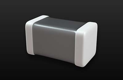
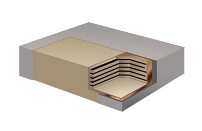
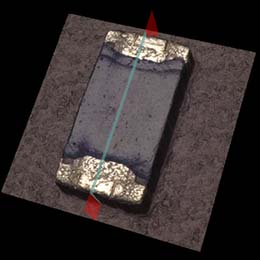
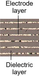
Measuring Multilayer Ceramic CapacitorsMultilayer ceramic capacitors are used to suppress noise and set circuit constants in electronic devices. A large number of capacitors are required in 5G base stations and mobile terminals. The demand for miniaturization requires that the layers be increasingly thin, requiring careful inspection for quality control.
Multilayer Capacitor Measurement ChallengesMetallurgical microscopes, stereo microscopes, and conventional digital microscopes are typically used to inspect ceramic capacitors, but reflectance from electrodes and the dielectric are so different that it’s impossible to view the entire capacitor at the same time. | Accurate Multilayer Ceramic Capacitor MeasurementsThe DSX1000 digital microscope has features that enable you to observe the shape of minute electrodes and dielectrics with uniform brightness. And thanks to the microscope’s telecentric optical system, we can guarantee the measurement accuracy of all DSX objectives and at all magnifications.
|
Measuring Electronic Component PackagesThe resin that wraps electronic components is called the packaging. It protects the elements and connection terminals and must also transmit signals and power. They are manufactured in a wide variety of shapes to fit various components’ blueprints. Because their fit is a critical factor, their shape must be carefully checked and measured.
Sample provided by KOSTECSYS CO.,LTD. Package Measurement ChallengesElectronic component packages have become extremely small (sub µm), and it is no longer possible to measure them using a standard measuring microscope. | Sub-Micron Package MeasurementThe OLS5100 laser microscope’s advanced measurement capabilities enable highly accurate 3D measurements of fine electrodes with guaranteed accuracy and repeatability.
|
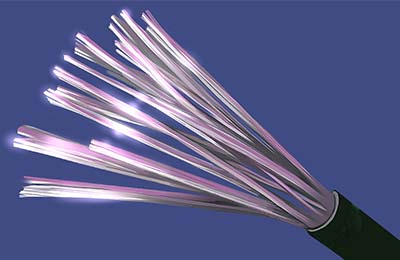
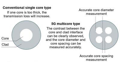
Measuring Optical Fiber Core DiametersOptical fibers are used as transmission lines since they’re not easily affected by electromagnetic noise. In 5G, multicore fiber is used to expand the transmission capacity, and the distance between each core as well as their diameter must be carefully controlled.
Optical Fiber Measurement DifficultiesWhen using a metallurgical or stereo microscope, it is often not possible to make observations with uniform brightness, leading to unreliable measurement data. | Accurate Fiber Core MeasurementThe DSX1000 digital microscope makes it simple to accurately measure optical fiber core diameters and core spacing with guaranteed accuracy and repeatability.
|
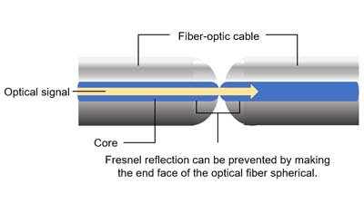
Measuring Optical Fiber End FacesOptical fibers are often connected to each other in a way that avoids attenuating light due to connection loss (Fresnel reflection). To prevent this, the fibers’ end faces are sphere shaped or inclined, but controlling this process can be difficult.
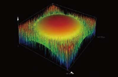
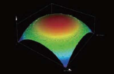
Fiber Optic End-Face Measurement ChallengesMeasuring microscopes and conventional digital microscopes cannot accurately measure the spherical shape or inclined shape of the end face. | Accurate Fiber Optic End-Shape DataThe OLS5100 measuring laser microscope uses 4K scanning technology to capture accurate data on spherical shapes and steep slopes that are close to vertical. Example of a spherical image
|
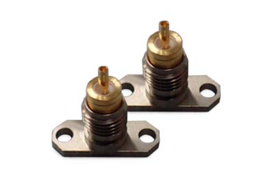
Measuring Fiber-Optic ConnectorsOptical fibers connect to base stations using coaxial connectors that dissipate heat efficiently, have minimal noise, and meet strict size standards. As part of the QA/QC process, the connectors are measured to make sure they meet requirements.
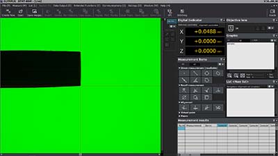
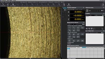
Conventional Measurement ChallengesOver time, coaxial connectors have gotten so small that they can no longer be measured using magnifying lenses or calipers. | Accurate Coaxial Connector MeasurementThe STM7 measuring microscope enables users to measure the length and height of fiber-optic connectors in the millimeter to nanometer range.
|
Need assistance? |
.jpg?rev=FFD6)
.jpg?rev=FFD6)
