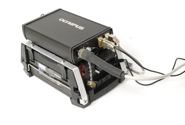
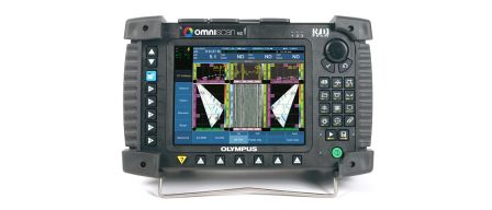
| Military and Commercial aircraft undergo countless non-destructive tests on routine intervals to ensure safe operation. Cracking caused from the stresses of take-off, flying and landing can be highly detrimental to the life-span of the aircraft as well as the safety of the crew, passengers and others. Some modern aircraft have over 6 million individual components, with as much as half that amount often being some type of fastener. Aircraft fasteners come in many shapes and sizes and are inspected using many Non-destructive tests (Ultrasonic, Eddy Current, Remote Visual etc.) for damage in and around the fastener either with the fastener in place or after removal. Being able to inspect the area around the fastener for damage without removal adds valuable time savings to the NDI process and prevents further damage from the removal process itself. A novel portable automatic scanning system for aircraft fastener inspection has been developed for various military aircraft (F5/T38) that also has promise for other aircraft. It has been coined “AFIS” (Automated Fastener Hole Inspection System). It is built around the popular OmniScan portable phased array system. | 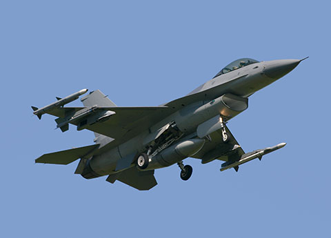 |
Damage Issue
The particular application to be solved with the AFIS was cracking at the Countersink and Faying surfaces in particular areas on the aluminum skin of the aircraft known to have these issues. Both aircraft suffered similar issues, with a main difference being that one aircraft had flush fastener heads and the other raised head and flush fastener types. Areas to be inspected were on the lower wing skin so access is from below the aircraft wing with minimal removal of components and limited spacing between fasteners.

Detail of Inspection Areas (side)
Conventional Methods of Inspection
Traditionally the inspection was done with a conventional single beam water filled shoe system that was manually spun by the operator. In order to project the single beam into the area of interest the system would have to be mechanically adjusted very finely for each area and 2 scans (clockwise and counter clockwise) were performed with each adjustment to be able to detect cracks at any orientation. This was time consuming as there was only one beam and adjustment was critical. Additional concerns included, no data storage, harder to get replacement parts, and repeatability.

Conventional Ultrasonic Scanner
AFIS System
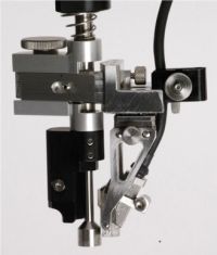
The AFIS system was developed with the following main components:
- OmniScan acquisition unit
- Motor Controller
- Automated Scanner with applicable centering device (raised head or Phillips style)
- 16 element Phased Array Probe(s) and Wedge(s) designed to be able to scan around the needed area
- Calibration plate with representable notches and fastener types


AFIS Operation
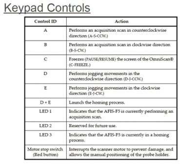
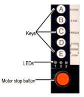
The AFIS system is able to project a sweep of beams at each interface simultaneously as shown below in a single scan. A centering device ensures proper probe spacing from the fastener center and the probe is scanned 360 + degrees around the fastener with a single button push. After the inspection the device automatically sets itself back into the home position for the next fastener. Almost all operation can be completed from the scanner interface including interval jogging, saving files, freezing the acquisition, homing, etc. Mechanical settings on the scanner allow for proper probe orientation for both CC/CCW scanning around the fastener. Only a fine mist of water based couplant is necessary and no paint removal is necessary. All different skin thicknesses are configured for on the calibration block, saved, and recalled for quick inspection from one fastener area to the next. Each area is typically viewed on the unit with an amplitude based S-Scan and C-Scan of the inspection. Low weight (around 2- 3 lbs. depending on configuration) was important as the unit must be used frequently and in an “above head” position. A light was added for low light conditions under the aircraft. All components can be housed in a single pelican case for easy transport and shipping. The past systems were designed to detect a .03-.05” notch at each surface per the requirements of the historical inspection but alternative sensitivities could be obtained.

Detail of Scan and Representable Instrument Layout

Detail of Typical Inspection Area and Applying AFIS scanner
Benefits of AFIS System
- Simultaneous inspection of faying and Countersink surfaces with a multitude of angles
- Automated scanning and full data retention
- Improved probability of detection with Phased Array Imaging and multiple angles
- Easy use with “at hand” control of most system commands via keypad on scanner
- Ergonomic light weight scanner with right and left handed keypad positions and multiple holding positions to lessen fatigue.
- Ruggedized for daily use in real world inspection scenarios under aircraft
- OmniScan based platform so system can be used for other inspections (UT/PA/EC/BT). (MX or MX2 possibilities depending on needs)
- Easy adjustment to varying skin thickness, fastener types and other inspection variables -(*Current tested thickness range approximately .180” to .660” and fastener diameters of 5/32”, 3/16”, 1/4”, and 5/16”. Current versions can accommodate both Phillips head and raised head fasteners).
- Adaption possible with portable flexible digital system (Heads up display glasses, Conventional UT spinning device for hard to reach areas, lateral sweeping configuration for hard to detect crack types, etc.)
- All analysis can be done directly on unit or in post analysis software. Digital alarming is also possible.
- Quick calibration verifications and adjustments
Conclusion
Olympus has developed and implimented a novel automated phased array system suitable for aircraft fastener hole inspection for 2 styles of military aircraft. It offers many benefits and is built around a flexible and portable concept which could be adapted to other aircraft fastener types and skin materials. Basing the system on the popular OmniScan acquisition unit allows flexibility to use the system for other ultrasonic and other NDT methods (MX based system offers modularity for EC/ECA/Bond Testing).
Note: The Scanning System detailed above have been designed with specific applications variables in mind.

