Application
Testing the integrity of metallic braze joints in metal tubing and other parts.
BackgroundBrazing is a common process for joining sections of small-diameter metal tubing and certain other small metal parts, such as electrical contacts. It bonds two pieces of metal by means of a metallic filler that is melted and then flowed into the space between them by capillary attraction. The process is similar to soldering. The filler metal, which is commonly an alloy of copper, silver, tin, and/or zinc with a relatively low melting point, must fill the space between the two parts being joined, wet the surfaces, and fuse them when it cools and solidifies. If the braze metal does not flow properly or does not fuse, the integrity of the joint is affected. This problem can usually be identified with an ultrasonic flaw detector. |
|
Equipment
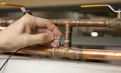
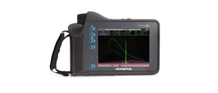
Most braze joints can be tested with an Olympus EPOCH® 6LT, EPOCH 650, or EPOCH 1000 ultrasonic flaw detector. Given the typical geometry of braze joints, small-diameter contact or delay line transducers are usually used. The transducer should be selected with respect to the geometry of the specific joint being tested, but for typical small-diameter tubing, the V208-RM (20 MHz) and V260 Sonopen® (15 MHz) transducers are most commonly recommended. Spring-loaded holders are available with these transducers as an alignment aid.
Procedure
Braze joints are typically tested using a straight beam test that monitors the amplitude of the echo from the braze location at the inner surface of the outer metal part. In the case of a good braze joint at the test point, the metal-to-metal bond will return a relatively small reflection, while an air gap at the test point will return a much larger reflection. These levels should be established in each specific case by setting up on reference samples representing known brazed and un-brazed conditions.
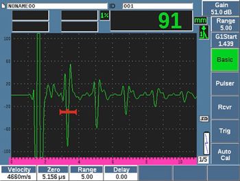
The example below represents typical echoes from a braze joint between 9.5 mm (0.4 in.) and 12.5 mm (0.5 in.) copper tubing that was tested with a V208-RM delay line transducer and a flaw detector. The first waveform shows a reference echo from an un-brazed area of the outer tube, which has been marked with a gate and set to nearly full-screen height. The second waveform shows the response from a properly brazed joint, in which the echo in the gated region drops to a very low level. It is followed by a larger peak representing the echo from the inside surface of the inner tube. By observing the amplitude of the echo within the gate, the operator can determine the joint condition at each test point by comparing the echo amplitude to these reference levels.
A partial braze within the area of the sound beam, due to conditions such as porosity, will typically be represented by a mid-level echo. Note: it is important to remember that very small discontinuities, such as pinholes that are a small fraction of the beam diameter, will not be detected through this procedure.
Typical echo response from a brazed joint, with a minimal echo in the gate.
Typical echo response from an unbrazed joint, with a large echo in the gate.


