Background
CRA-clad pipes are increasingly used for the transport of hot and corrosive materials because of the higher resistance to corrosion provided by the corrosion resistant alloys (CRA) used for the pipe cladding. However, the layer of protection that these alloys provide also impedes effective ultrasonic inspection of dissimilar girth welds in the piping. The industry has been searching for a simple and reliable solution to this particular challenge.
Problematic
Ultrasonic inspection of dissimilar girth welds in CRA-clad piping poses a particular challenge. As the material of the clad layer (Inconel, stainless steel, etc.) differs from that of the parent material (carbon steel), the quality of the interface between these materials makes the rebound on the internal wall (ID) of the pipe unpredictable or even impossible. In addition, the anisotropic structure of the cladding and the weld creates ultrasonic mode conversion and different beam orientations. Consequently, high-precision techniques like zone discrimination cannot be used. Pulse-echo using the second leg of the ultrasonic beam is impossible, which makes inspection of the cap and its subsurface extremely challenging.
Solution
Olympus has developed a dual matrix array (DMA) probe with the goal of increasing the capacity for detection and sizing of flaws that are located at the root, in the volume, and on the surface of dissimilar welds of large-diameter clad pipe. (For more details about dual matrix array, please consult the application note: Dual matrix array for the inspection of acoustically noisy welds.)
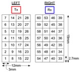
The tests discussed in this application note were performed on a 36-inch pipe sample, using a 2.25 MHz DMA probe composed of 2 matrices of 28 elements (7 × 4) mounted on a 55-degree LW wedge.
A portable phased array instrument, the OmniScan MX2 32:128 PR, was programmed to assure full coverage of the weld without skipping off the internal wall of the pipe. Two different groups were used:
- Group 1 with a sector scan from 30 to 76 LW focused at 2 mm deep to provide coverage of the upper volume of the weld and the surface
- Group 2 with a sector scan from 30 to 76 LW focused at 20 mm deep to provide coverage of the root and the volume of the weld
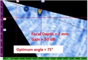
The picture below shows the modeling of the beams generated at the interface between the 2 matrices.
 |  |
Beam modeling representation: (on the left) 75 LW beam focusing at 2 mm [part of group 1 ]; (on the right) 45 LW beam focusing at 20 mm [part of group 2]
The inspection was done manually without the use of a scanner or an encoding device.
Equipment
The following equipment was used for the inspection:
|
Phased array instrument:
1 dual matrix array probe: 1 flat wedge: Software: |
OmniScan MX2 32/128 PR (U8100149)
2.25DM7X4PM-19X12-A17-P-2.5-OM (U8331715) SA17-DN55L0-IHC (U8831948) NDT SetupBuilder Software 1.0R5 TomoView (optional) |
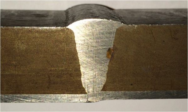
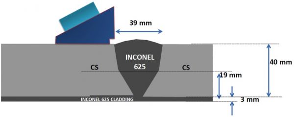
The mock-up used for the tests was a 36 in. diameter pipe composed of carbon steel with a 3 mm thick mechanically bonded cladding of Inconel 625. The material of the weld was composed of Inconel 625 as well.
The set of reference defects for the mock-up is shown below. They include: 2.5 mm side-drilled holes located in the center of the weld at T/4, T/2, and 3T/4, as well as 10 mm long and 2 mm deep surface notches located at the toe position, at the top of the weld, and at the root.

Schematic of the reference defects of the clad-pipe mock-up
Results
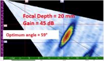
All SDHs were detected with a SNR superior to 45 dB. The SDHs located at 3T/4 and T/2 were detected with group 2 focusing at 20 mm, and the SDH located at T/4 was detected with group 1 focusing at 2 mm.
The toe notch located on the same side of the probe and the notch located at the top of the weld were detected with a SNR superior to 40 dB and by focusing group 1 at 2 mm (as shown below). The notch located at the root was easily detected with group 2 focusing at 20 mm; however, the picture was not recorded.
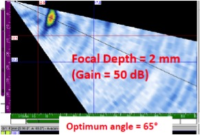 | 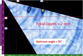 |
Detection of notch located at: (on the left) toe position; (on the right) at the top in the center of the weld
Important to Note
The results presented in this application note concern the use of a 2.25 MHz DMA probe on a large-diameter clad pipe. The results that are discussed in this application note cannot be transferred to smaller diameter pipes. For small-diameter pipes, please refer to the application note "Inspecting Small-Diameter, Austenitic Steel Pipes using a Dual Linear Array (DLA) Probe."
Also, this inspection was done manually without a scanner or an encoder. While this technique is flexible, it is also operator dependent. Therefore, these results cannot be transferred as is to a high-production-rate environment. Olympus is also in the process of developing solutions for this type of environment with the use of similar tools.
Conclusions
A 2.25 MHz DMA probe paired with the OmniScan MX2 32:128 PR can be advantageous for the inspection of clad pipe with large diameters. Full coverage of the dissimilar weld was ensured. SDHs located in the volume and notches located on the ID and OD can be detected using an inspection scenario of two groups steering the beams from 30 to 76 LW, focusing at 2 and 25 mm.
These results are very promising, and Olympus is intent on further developing this strategy to extend the use of these tools to smaller clad-pipe diameters and high-production-rate environments.
