Introduction
The nondestructive testing (NDT) industry is experiencing an important technological advancement, as total focusing method (TFM) capable inspection devices are making their entry into the market. The TFM approach represents a significant step forward for phased array ultrasonic testing (PAUT) technology. However, some PAUT practitioners may still be confused about TFM and its relation to full matrix capture (FMC), as well as the differences between conventional PAUT and TFM/FMC processing. This application note provides a basic understanding of TFM imaging for people who are familiar with PAUT imaging. For conciseness and clarity, aspects related to ultrasound propagation modes are set aside.
Conventional Phased Array Ultrasonic Testing (PAUT) Imaging
The hallmark of ultrasonic phased array is the capacity to focus and steer an acoustic beam at a desired position in an inspected part. The phased array focusing approach uses delays, applied on both the transmission and reception elements of the phased array probe, to synchronize the time of flights of short, pulsed waveforms at the position of interest. At the focal zone in the specimen, the width of the generated acoustic beam narrows, and the corresponding detection resolution increases dramatically.
Physical Beamforming
Conventional phased array uses the physical superposition of elementary acoustic waves in transmission to produce an acoustic beam aimed at a specific focused depth in the inspected piece. The set of transmitter elements form an aperture from which a coherent acoustic pulse emerges. The action of conventional phased array transmission is referred to as “physical” beamforming. In an S-scan, for instance, physical beamforming acquisition occurs for each user-specified angle.
Synthetic Beamforming
At the end of the acoustic loop between the transmitter, the scatterer, and the receiver, the elements that compose the receiving aperture register all returning echoes from the inspected part as A-scans. A-scan data contains the echo amplitude and transit time. To accentuate the sensitivity of the reception in a specific region of the part, the A-scans are delayed and summed as if focusing were to be applied through physical beamforming. This time, however, all the delays and summations occur in the software of the acquisition device. This reception beamforming is referred to as “synthetic” beamforming. All computations required for the synthetic beamforming are carried out in dedicated front-end electronics, enabling fast-paced, real-time imaging.
Limitation of Conventional PAUT
The benefit of phased array focusing is a clear improvement in sensitivity in the focal zone, which locally increases the detection performance. However, this augmented sensitivity is limited to a controllable, yet fixed depth in the inspected part. Reflectors located outside of the focal region appear blurry and somewhat larger than an identical reflector appearing in the focal zone.
FMC–An Acquisition Strategy
TFM–Image Reconstruction
TFM—The Construction of a Highly Resolved Image
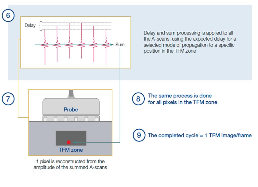
The total focusing method (TFM) is the systematic application of the basic focusing principle of phased array in a defined region of interest (ROI) in an inspected part. The ROI is segmented into a grid of positions, or “pixels,” and focusing through phased array beamforming is applied to every pixel in that grid. To date, TFM is the most efficient method to generate this ROI image that is focused everywhere and at every depth.
However, if the PAUT acquisition strategy through physical beamforming acquisition were used for the total focusing method, the time to generate a single TFM image would prohibit any deployment for most NDT applications. With the TFM, the number of pixels constituting an image is much higher, for instance, than the number of discrete angles required to generate an S-scan covering the same region of interest. An S-scan that is swept through 100 angles requires 100 acquisitions through physical beamforming, whereas a TFM image of 100 × 100 pixels would require 10,000 physical beamforming acquisitions.
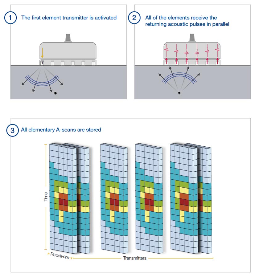
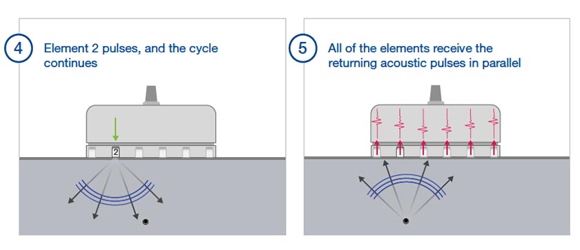
To avoid this problem, another acquisition strategy is used, in which the amplitude values in the grid are calculated through synthetic beamforming for both the transmission and reception phases. This strategy requires a set of focal laws corresponding to each pixel position over the ROI grid, and a set of raw, fundamental waveforms, or elementary A-scans. An efficient way to obtain this set of elementary A-scans is full matrix capture (FMC) data acquisition.
FMC—An Acquisition Strategy for Productive TFM
Full matrix capture (FMC) is an acquisition process that obtains all the A-scans (amplitude time series) between all individual pairs of transmitter and receiver probe elements. These elementary A-scans are stored in the FMC data set. To achieve the best focusing result, all of the elements constituting the full aperture of a probe should be used to generate the FMC data set through synthetic beamforming. In this case, the number of acquisitions required to build the FMC data set is equal to the number of elements of the probe. The FMC data set contains all the sound propagation information between each element of the probe, including reflections at interfaces and scattering by flaws. Any type of PAUT acquisition can be reconstructed from the FMC data set using adequately chosen delays, including a sectorial scan, plane wave imaging (PWI), dynamic depth focusing (DDF), total focusing method (TFM), etc.
Using the FMC acquisition process, the number of acquisitions required to generate an image may be about the same as PAUT, but processing the individual FMC data sets requires significant storage capacity, transfer bandwidth, and computational power. Depending on the electronics of the device used, obtaining the TFM/FMC results can be slower than conventional PAUT.
Illustrating the Differences between PAUT and TFM Images on an Experimental Case
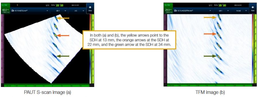
To illustrate the differences between PAUT and TFM imaging, a setup is presented in which a linear phased array (PA) probe is used to scan identical side-drilled holes (SDHs) that are vertically distributed in a steel block.
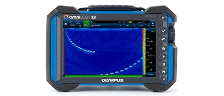
A PAUT S-scan (a) and a TFM image (b) obtained with the same inspection configuration, an OmniScan™ X3 flaw detector, 5L64-A2 probe, SA2-N55S-IHC wedge, and using a 32-element aperture, are presented here.
In the PAUT S-scan (a), each A-scan is acquired using a unique focalization depth of 22 mm. SDHs located in the focal area appear with similar amplitude and size. SDHs located far from the focalization depth appear distorted and with a lower amplitude. Several images with various focalization depths are needed for a more uniform sizing of all the SDHs in this test part.
In the TFM image (b), ultrasound beams are focused at each pixel. As can be seen, each one of the SDHs appears with an optimal resolution. Nevertheless, some distortions are still observed for SDHs located at the extremities of the region of interest. These distortions are intrinsic to the beamforming process common to both PAUT and TFM imaging.
Summary of the Discussion of TFM vs PAUT
The principal advantage of TFM is that the entire image is displayed with focused amplitude, compared to an image produced with PAUT, which is only highly resolved in the focal area of the beam.
The synthetic beamforming performed only on the receiving end in conventional PAUT is also done in the transmission phase in TFM to make the acquisition rate acceptable for NDT applications. The synthetic beamforming requires the application of specific delays on elementary A-scans acquired through FMC. Note that the FMC data set can provide basic data to any synthetic beamforming, including both PAUT and TFM.
Because of the large amount of FMC data that must be processed to produce a TFM image, the total focusing method may imply lower productivity than PAUT with the same aperture.
Although the TFM image is highly focused over the entire region of interest, it remains affected by the same acoustic limitations that hamper PAUT. Amplitude fluctuations and distortions are observed in both PAUT and the TFM, but the results for a set of identical scatterers in an inspected part are more consistent for the total focusing method.
