This post features the 38DL PLUS™ ultrasonic thickness gauge, which has been replaced with the 39DL PLUS™ model. Please refer to the 39DL PLUS web page for the latest information on its features and capabilities.
Asset Reliability Inspections (ARI) is an asset integrity/compliance company located in Western Australia that offers pressure equipment inspection, pressure equipment design verification, weld inspection, and nondestructive testing (NDT) services to the Asia-Pacific region.
Founded in 2008, ARI provides a diverse offering of NDT and inspection services to many industrial sectors, including mining, power generation, fabrication, oil and gas, and transportation sectors, such as rail.
The company assists asset owners with compliance and in-service NDT, helping to monitor and assess the condition of aging infrastructure. Their inspection services for tanks and pressure equipment are complemented by NDT to give them additional information on the condition of their assets.
One piece of NDT equipment they rely on is our 38DL PLUS™ (38DLP™) ultrasonic thickness gauge, which they use across all the industry sectors for in-service applications. We chatted with Neil Young, General Manager of ARI, to learn how the thickness gauge helps with their process and what they like about the instrument. One key aspect that stands out to them is its ease of use.
“The 38DLP is one of the most user-friendly and intuitive products on the market,” stated Neil.
Keep reading to learn how this easy-to-use thickness gauge helps ARI tackle complex inspection challenges.
The Challenge: Inspecting Aging Infrastructure
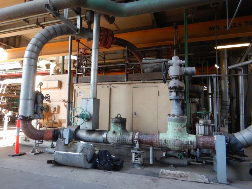
A large infrastructure area, mapped out and ready for testing
Industrial infrastructure equipment, such as pressure vessels, can continue in operation for several years up to decades. Over time, however, all equipment will eventually fail. The implications of industrial infrastructure system breakdowns and failures are staggering—it’s a concern to asset owners in terms of customer reliability, safety, and the operating costs of equipment.
Common Causes of Aging Infrastructure
Infrastructure equipment can deteriorate in-service from various causes, which can include:
- Sustained heating
- Insulation degradation
- Wear and material fatigue of mechanical parts
- Corrosion from chemicals in the air or from by-products of material deterioration
- Damage by vegetation, insects, animals, and humans
- Natural disasters, such as tornadoes, hurricanes, earthquakes, and floods
- Natural elements, such as sun, wind, rain, ice, and snow
The infrastructure asset management services that ARI provides offer a solution to help asset owners safely and confidently continue to manage and operate their aging equipment without failures or unplanned shutdowns.
According to "The economics of aging infrastructure" article published in IEEE Power and Energy Magazine, an effective infrastructure asset management approach is to catalog, track, analyze, and predict aging across infrastructure systems, then use this information to better manage aged equipment and costs.
The article also recommends applying NDT inspection to extend lifetimes, reduce costs, and mitigate reliability problems. This is considered a sustainable approach to infrastructure asset owners—one that accommodates and manages aging and its effects over the long run.
Inspecting Complex Geometries of Infrastructure Assets
In addition to the challenge of aging infrastructure, the complex geometries of infrastructure assets present another challenge. Performing inspections on complex shapes with changing geometries, such as pipe elbows and valves, is laborious, and many industry solutions aren’t suitable for these items.
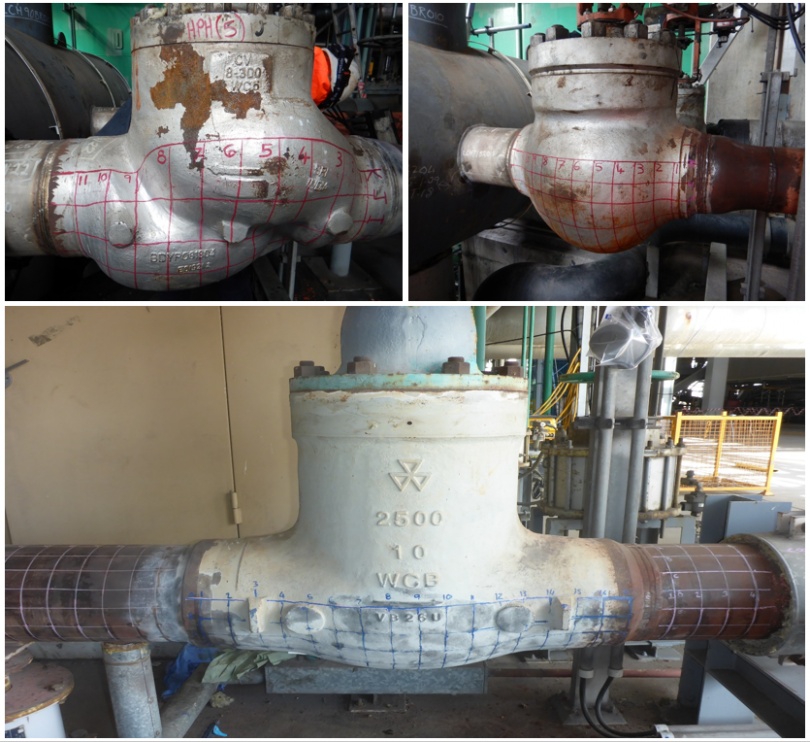
Some examples of complex infrastructure shapes, mapped and ready to be measured
To inspect these assets, the items must first be mapped in plots on their surface, then measurements are taken systematically.
“Aging infrastructure requires assessment for continued use. The best use of NDT is when you understand the degradation method you are trying to detect, and, therefore, you can select the best NDT method to find this degradation,” said Neil.
Neil elaborated, “As there is a direct relationship between remaining strength and the wall thickness of infrastructure, there is always a need for a reliable thickness gauge.”
The Solution: An Easy-to-Use Ultrasonic Thickness Gauge
Ultrasonic testing (UT) is an effective NDT method that induces short, high-frequency ultrasonic waves into solid objects, typically metal or composites. Traveling sound waves are affected by irregularities, such as cracks or voids.
UT thickness gauges can collect these sound waves as they reflect or pass through a material being scanned. By collecting and analyzing these returned waves, the interior structure of a system can be mapped and compared over time.
“Our Olympus [UT] thickness gauges are a valuable asset to ARI, and we own several of them to meet our clients’ needs,” said Neil.
ARI has been reliably using Olympus thickness gauges for their in-service NDT inspections for many years. They were early adopters of previous Olympus thickness gauge models, such as the 26DL, MG2, and 36DL PLUS.
Today, ARI prefers to use the 38DL PLUS instrument for their in-service inspections.
“The functionality of the Olympus 38DLP is consistent with current and previous Olympus thickness gauge models, making the transition seamless,” offered Neil. “This means that someone who is familiar with UT, but not necessarily Olympus products, can readily use the 38DLP with ease.”
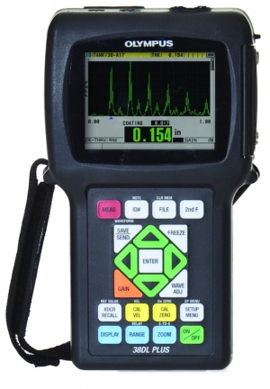
The 38DLP ultrasonic thickness gauge
There are so many features of the 38DLP thickness gauge that ARI likes, that Neil couldn’t name them all.
“The main features we like are:
- The ‘plug-and-play’ connection and the GageView™ interface program that comes with the 38DLP, where we can easily transfer our field results to Microsoft Excel files for reporting with ease
- The large, easy-to-view screen (in all [ambient] conditions)
- Probe recognition of Olympus probes that automatically calculate V-path correction, meaning we have confidence in readings that are taken outside of the calibration block thickness
- Automatic Gain Control (AGC), so that we do not need to adjust the signal for each measurement
- The waveform is saved as well as the thickness reading (great for explaining the results with the team when back at the office)
The 38DLP is one of the most user-friendly and intuitive products on the market. With its full-size, easy-to-read screen and keypad display buttons, there is no need to go searching through non-intuitive menus to find the functionality you are looking for,” Neil explained.
Powerful Data Logging Capabilities Streamline UT Inspections
As previously mentioned, UT thickness gauge inspections can be laborious and time-consuming—thousands of individual measurements recorded in the field and painstakingly compiled. If the thickness readings are recorded by hand, then data entry errors can cause confusion for asset owners.
“Before thickness gauges came out with data logging features, we were required to manually keep a record of measurements on paper, which required a second person in the field to write and assist as a scribe, recording results while the thickness testing technician took measurements,” said Neil.
Not only was this process time-consuming, but it led to extra costs and an increased risk of human errors.
“The second person came with an additional cost to the client and increased sources of [human] error from handwritten raw data, which then needed to be transferred to electronic means for inclusion into a final report,” Neil detailed.
Neil continued, “Therefore, we were very pleased when the 38DLP came out with powerful data logging capabilities with 2D, 3D, and even manual measurement points as a standard feature.”
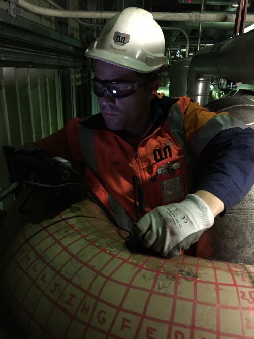
The 38DLP thickness gauge is rugged, portable, and can access infrastructure assets of complicated shapes and geometries, like this mapped pipe elbow
Neil explained how this streamlines their process.
“99% of our work is a simple 2D grid, where we are required to report the thickness results of a pressure vessel, pipe, or plate,” said Neil. “After we have identified our grid naming convention (letter and the number directions) and the size of plot spacing (depending on the need), we simply create the 2D file on the [38DLP] in the field, and then save the thickness results directly onto the gauge as we work our way through.”
Neil continued, “If we come to an area that has an obstruction where we cannot take a reading for that data point, we simply click the ‘Save’ button with no data on the screen, and the 38DLP will move on to the next point.”
The Results: Exploring a Recent UT Inspection of a Pressure Vessel
For one of their recent in-service inspections, ARI was required to assess a heater in a power station (i.e., a type of pressure vessel) for its suitability for continued safe use. In this case, there is a large inlet pipe attached to the pressure vessel, and the flow from this inlet pipe causes flow accelerated corrosion (FAC).
This means the inside of the vessel wears away due to the flow from its standard operation. It’s ARI’s job to find and assess this loss of thickness so that the power station can continue operation confidently.
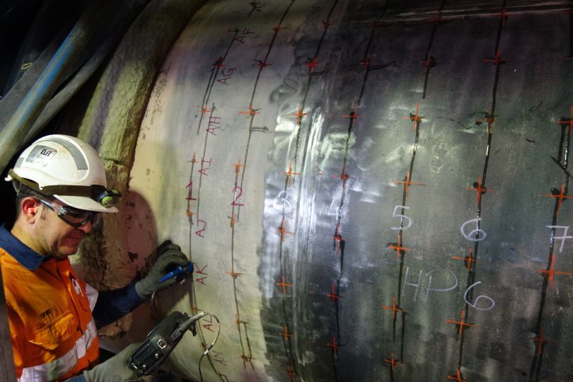
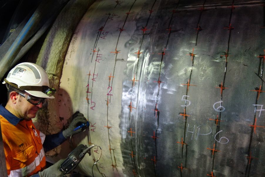
An ARI inspector uses the 38DLP instrument for ultrasonic thickness testing on pressure equipment
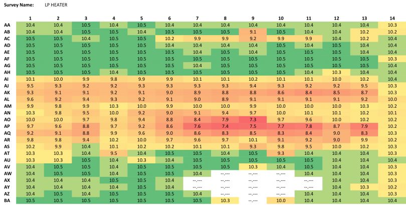
The pressure vessel cannot be accessed on the inside due to its design. Even if it could be accessed on the inside, the degradation might not be readily seen. The mapped data area shown above containing no readings is where the inlet nozzle is located (the cause of the FAC).
In this example, ARI had a large area to cover, so a 150 × 150 mm (6 in. × 6 in.) grid was used to trend wall thickness loss. ARI exported the results into Microsoft Excel using the GageView interface software program, selected the results in Excel, and then used the Conditional Formatting feature, which automatically colors the cells in order of thickness from high to low.
ARI can then take these results and compare them to the last inspection they conducted on this same asset to calculate a wastage rate. If areas are identified for further assessment (e.g., if the results were outside the allowable loss), then an additional 2D grid can be performed over these areas with a smaller grid size, such as 50 x 50 mm (2 in. × 2 in.).
Neil explained, “This pictorial representation of the results via the data logger and GageView ensure rapid and easy-to-interpret results for all parties.”
Effective Results without Breaking the Budget
Neil finds that the costs of the 38DL PLUS instrument are just as effective as the results.
“The best part of this [38DLP] thickness gauge solution for the client is the cost to them, as this is a solution that gets effective results without breaking the budget,” Neil said. “We often see awfully expensive equipment and bespoke solutions to find degradation—but the simplicity, the confidence of the results, coupled with the price of the 38DLP is often overlooked in an application like this.”
He continued, “There is no need to mobilize large equipment, NDT specialists, or advanced operators—the Olympus 38DLP can get results in an efficient, repeatable, and reliable manner, which is readily achievable for every owner of the 38DLP.”
Related Content
Corrosion Thickness Gauging with Dual Element Transducers
Ultrasonic Thickness Gauge Tutorial
