Application
Using ultrasonic testing to identify the presence or absence of bonding between an outer layer of high impedance material, such as metal or ceramic, and an inner layer of low impedance material, such as plastic, composite, or rubber. This technique also applies to many metal-to-metal glue joints.
Background
When materials of similar acoustic impedance (density multiplied by sound velocity) are joined to each other, such as metal welded or brazed to metal, or plastic fused to plastic, the presence or absence of bonding can usually be determined from the amplitude of the first reflection from the boundary. Typically, there will be a significant difference in reflected signal amplitude between bonded and disbonded conditions. However, if there is a large difference in the acoustic impedance of the two materials, as in the case of bonds between metal and polymers, then that acoustic impedance mismatch will cause a significant reflection from the boundary even if the materials are mechanically bonded. The change in echo amplitude between bonded and disbonded conditions may be small and hard to detect, especially in situations where transducer coupling conditions are not uniform. This same situation often occurs in cases where metal is bonded to metal by means of epoxy or other low impedance adhesives. Unless the adhesive layer is extremely thin, it will constitute a low impedance bond line with a significant reflection, even from a good joint.
Note that in cases where the low impedance material is on the outside, or part geometry otherwise permits coupling to the low impedance side of the joint, then the recommended procedure is a phase shift test. This is described in the Olympus application note on Phase Shift Test for Bond Integrity. In cases where the test must be performed from the high impedance side of the joint, the ringdown technique described in this application note is often the best approach. This involves observing a series of multiple reflections from the boundary and looking for a difference in the rate at which the amplitude of successive echoes, or the ringdown envelope, changes between bond and disbond conditions. As the sound wave reverberates in the metal or other high impedance material, the amplitude change is multiplied at each bounce. For example, a hard-to-see 5% amplitude drop between disbond and bond conditions at the first echo becomes a 25% drop at the fifth echo and a 50% drop at the tenth echo. While the change in a single echo may be small, the collective change across a series of echoes will be much larger and easier to identify. In a typical joint, bond and disbond conditions will each produce their own distinctive ringdown pattern. | 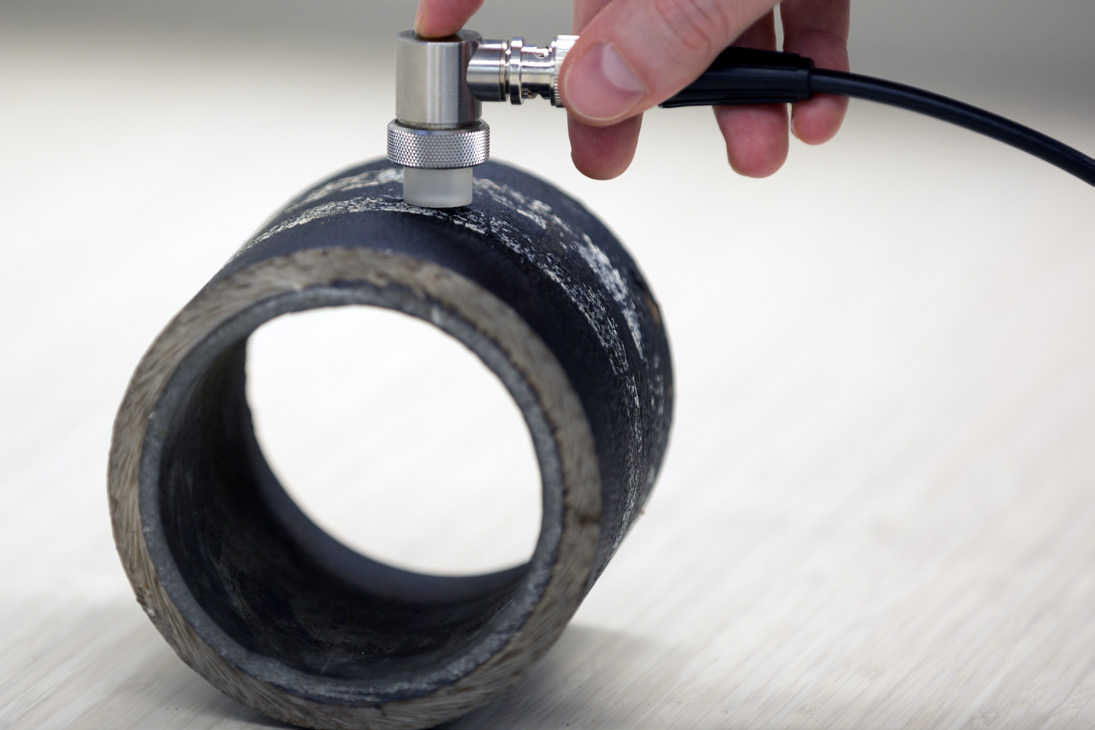 |
Equipment
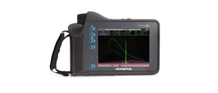
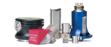
This test can be performed with any standard ultrasonic flaw detector, such as the EPOCH® 650 or EPOCH 6LT flaw detector. Ultrasonic pulser/receivers can also be employed. The transducer will usually be a common delay line transducer in the frequency range between 2.25 MHz and 20 MHz, such as a V207-RB, V206-RB, V202-RM, or V208-RM. The specific transducer for a given test will be selected based on material thickness, geometry, and acoustic properties.
Procedure
Set gain such that the first backwall echo from a well bonded reference sample is at 80% screen height, and set screen range large enough to display a series of backwall echoes. In the first waveform below, the first peak is the delay line interface echo, and the subsequent peaks are multiple backwall echoes from 0.1 in. (2.5 mm) steel bonded to a plastic liner. Because the metal is bonded to a backing material, the bonded polymer on the back side of the steel acts as a mechanical damping mechanism, and the echoes decay relatively quickly. It is helpful to use the DAC function to draw a curve marking the ringdown envelope from a known good bond.
Slow ringdown pattern from bonded metal, DAC curve set as reference:
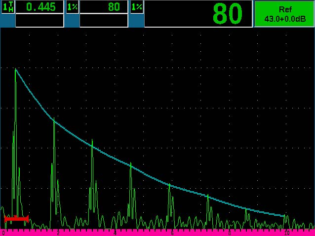 | If these two materials are disbonded, the damping effect is removed and the peaks become larger, rising above the reference curve as seen below. |
Ringdown pattern from disbonded metal, peaks rise above reference curve:
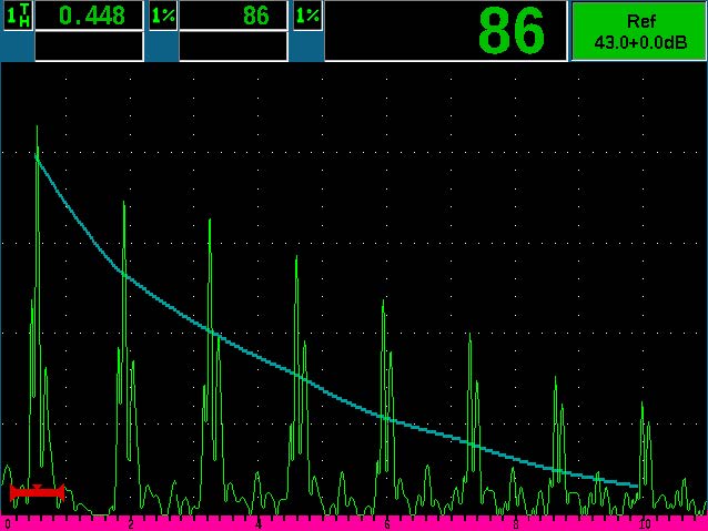 | Notice that the relative amplitude of the multiple echoes increases more rapidly towards the right side of the screen. The exact variance in the ringdown pattern between bonded and unbonded conditions will depend on the relative acoustic impedance of the two materials as well as attenuation factors, but in principle this test works for any situation involving a high impedance material bonded to one of low impedance. By recording the two characteristic patterns observed in the reference standards and comparing them to the waveforms from a test piece, the presence or absence of bonding in the test piece can be determined. It is important to remember that this type of test qualifies the presence or absence of bonding only, not the strength of bonding. Also, the materials must be acoustically bonded by an adhesive or similar bonding agent. Pressure alone is rarely sufficient to create an acoustic bond. |

