Summary
Visual inspection with ultraviolet (UV) light relies on the principle of fluorescence. Fluorescent material glows in the visible spectrum, but it requires light with a higher frequency wavelength to provide enough energy. Inspectors use ultraviolet light, which is invisible to the human eye, but not to the digital CCD chips used in industrial videoscopes. Choosing the right ultraviolet filter is an important component in the process of using fluorescent material to highlight small hairline cracks.
Introduction
RVI with ultraviolet dye penetrant enables users to detect much smaller hairline cracks in the material being inspected. The surface being inspected is sprayed with a fluorescent liquid dye. Through capillary action, the liquid penetrates into very small cracks. The surface is then loosely cleaned with a quick rinse. An ultraviolet light source is then placed over the area while visual inspection takes place. The fluorescent dye glows brightly under the ultraviolet light. When used with an Olympus videoscope, this procedure enables users to find small cracks that are not immediately visible to the human eye.
Solution
Some points to consider when inspecting hairline cracks with fluorescent dye include:
- Many applications require the inspection of cracks too small or thin to see without assistance.
- Water, with its high surface tension, naturally penetrates into these small cracks.
- Utilizing this capillary action, fluorescent dye can penetrate into these cracks as well.
- An ultraviolet light source will make the fluorescent dye in the cracks glow.
- An ultraviolet filter helps to control what kind of light reaches the CCD chip, enabling a more effective inspection image.
Applications
Applications where high heat is applied directly to metal, such as welding and forging, can cause enough stress to produce very small cracks. It is very difficult to consistently see these cracks with the human eye. While their length may vary, the crack’s width is almost always very thin.
A high level of continually applied static stress can cause cracks in areas such as:
- A joint between two large, separate parts
- Next to a hole in a part (i.e. the hole creates a shorter section of the structure where more stress is concentrated)
- The heads and threads of bolts
Fluorescent Dye Penetrant
The following are the steps commonly used when applying a fluorescent dye penetrant to a component to look for small cracks. These methods may differ based on the application.
- The user sprays the area with a fluorescent liquid and allows it to sit for about 10 minutes. This allows the liquid, through capillary action, to settle into all of the tiny cracks.
- The material is quickly rinsed then dried. This is done fast enough that the dye in the cracks is not disturbed or pulled out.
- Occasionally, a developer is then applied to the area. This makes the dye even more fluorescent and easier to spot.
- The part is rinsed again as needed.
As per ASTM standard E1417 Section 6.6.1.1 for fluorescent dye penetrant inspection, (http://www.astm.org/Standards/E1417.htm), the intensity of the ultraviolet light should be a minimum of 1000 μW/cm2 at the viewing distance being used.
Fluorescence
Fluorescence is a kind of luminescence that differs from reflection. Reflection occurs when light strikes a surface. That light then bounces off and travels in a different direction. In reflection, the light has very little interaction with the surface being struck.
Fluorescence starts when light of a higher energy strikes a surface. The material in that surface absorbs the light’s energy. This causes the electrons in the atoms of the fluorescent substance to become excited and unstable. In order to stabilize, the electrons lose some of their energy by emitting light. The emitted light is always at a lower energy than the light that first struck the substance.
In fluorescent dye inspection, a videoscope with an ultraviolet light source is used. The videoscope is first used to navigate to the area to be inspected. The TrueFeel articulation on Olympus videoscopes makes it easy to locate and navigate to the target area. This is crucial as an external light source may have to be used. The videoscope will then have to carry the light guide even though it may be very small.
Next, ultraviolet light is shone on the surface of the area treated with the fluorescent dye, which will glow in its presence. The industrial standard for ultraviolet light is a wavelength of 365 nm. The fluorescent dye most commonly used emits light with a wavelength of 550 nm. The dye absorbs the higher energy 365 nm light then emits the lower energy 550 nm light.
Ultraviolet light is commonly called “black light” because we cannot see it. However, we can see fluorescent light in the 550 nm range; it appears as a yellow-green color. The UV light is being reflected off of the material but we do not see it. This is why the fluorescence seems to glow so brightly; we do not see the UV reflection around the fluorescence.
CCD chips, like the ones used in videoscopes, can detect the UV light. They pick up cracks highlighted by fluorescent dye and the UV reflection. Every digital CCD imaging system has an automatic gain feature which brings down the brightness of the entire image if the image as a whole is too bright. Since the chip can see the UV reflection, the image is darker than it needs to be because the UV reflection is forcing the imaging system to lower the brightness.
When a UV filter is placed in front of the CCD chip, the UV reflection will not show up on the image, only the fluorescent crack. Then, the CCD chip behaves more closely to the human eye and enables the crack to appear much brighter.
Applicable Products
Olympus offers three different UV light source solutions for inspecting with fluorescent dye penetrant. The two main considerations are brightness and portability.
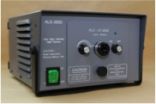
ALS-UV3000
| The ALS-UV3000 is our brightest UV light source. It requires the use of a special light guide that shrinks down to fit in smaller areas. This light source is a desktop unit and must be plugged into an AC outlet. We recommend that a UV filter be added to the tip adaptor. |
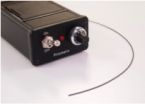
PRIZ UV Light Source
| The PRIZ UV LED light source is our most popular UV light source. It maintains the required brightness while also being very portable. It runs on two 9 V batteries. The included light guide is only 0.5 mm, making it easy to add to any inspection. We recommend a UV filter be added to the tip adaptor. |
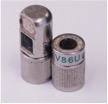
UV Tip Adaptor
| UV tip adaptors are the most portable option. They require an IV8 videoscope (6.0 mm or 4.0 mm). While standard tip adaptors have LEDs that generate white light, these adaptors generate UV light. They have a UV filter installed in the lensing system so adding additional filters is not necessary. |
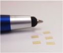
UV filters
| Pre-cut UV filters are available for the ALS-UV3000 and the UV LED options. They can easily be added to the interior of the tip adaptor. |
Conclusion
Certain stresses can cause very small cracks that are difficult to see. Using ultraviolet light on a surface pre-treated with fluorescent dye penetrant enables inspectors to easily spot any cracks. Click the link below to find your local representative and ask them about Olympus UV dye penetrant inspection solutions.
Appendices
Standard practice for liquid penetrant testing: www.astm.org/Standards/E1417.htm

