8.3 AWS D1.1
AWS D1.1
The American Welding Society Structural Welding Code section D1.1 defines an established technique for classifying discontinuities in welds according to a “D rating” that is calculated as follows:
A – B – C = D where
A = Discontinuity indication level in dB
B = Reference indication level in dB
C = Material attenuation factor, (2x [soundpath length in inches – 1 in.]) expressed in dB
The inspector then compares the calculated indication rating D to an acceptance/rejection table provided by AWS in order to classify the severity of the discontinuity. As an inspection proceeds, the operator develops an AWS report that lists the variables above as well as transducer information, discontinuity length and location, and the inspector’s evaluation.
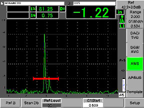
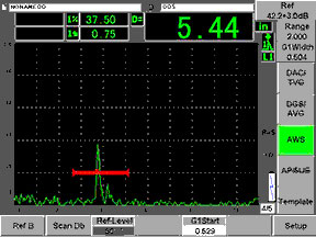
Contemporary flaw detector software simplifies this process by incorporating the D-rating calculation into the display and recording A, B, C, and D values in stored test records. In setup, the operator records a reference amplitude level B from a specified side drilled hole reflector. When testing, the instrument measures indication amplitude and sound path length to obtain values for A and C and then calculates the D-rating, which can be either positive or negative depending on whether the reflector echo is smaller or larger than the reference echo used in the setup. In the example below, the flaw indications in the red gate have D-ratings of -1.22 and +5.44, respectively indicating relatively large and small reflectors.
 |  |