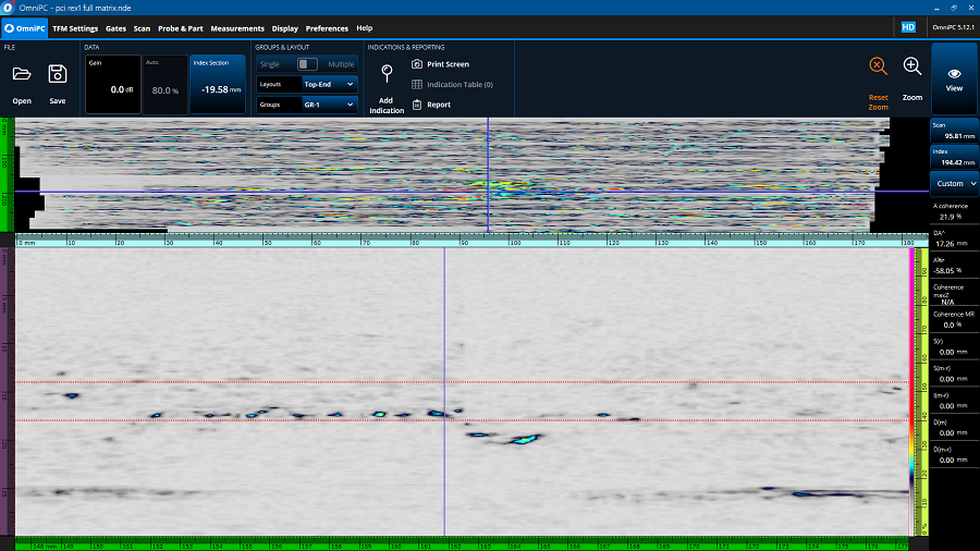
A: The phase of an A-scan refers to the frequencies that make up the signal at any given point. Because of the effects of constructive and destructive interference, the A-scan can be described by the phase portion that dictates the signal frequency and an amplitude portion. In phase coherence imaging (PCI)—a variant of total focus method (TFM) imaging—comparing the phase information between A-scans and the level of similarity in their frequency distributions determines the phase coherence. The greater the similarity between the frequency distributions of the A-scans, the higher the level of coherence.
A: Since defects reflect or diffract the ultrasound wave, the phase of the returned signal from these defects will be centered in a small band near the probe frequency. Conversely, the phase of background noise has no central frequency and covers a wide band. When multiple A-scans return the same central frequency in a small band at the same position in the TFM zone, they are coherent. The higher the level of coherence, the higher the certitude that there is a defect at that position.
A: With PCI, the signal amplitude is not considered at all when generating the TFM images. So even in materials with high attenuation or background noise, the coherence of the signal can still be evaluated since the frequency distribution can be found even with low signal amplitude.
A: The OmniScan™ X3 64 flaw detector’s phase coherence imaging is live, so the PCI images are displayed on the screen in real time during your inspection at roughly the same speed as its conventional TFM images are produced. Even though there is an additional processing step with PCI, the time it takes is negligible due to the device’s powerful, high-performance data processor.
A: The OmniScan X3 64 flaw detector’s PCI technology (integrated into the MXU 5.10 update) is capable of live data processing during scanning, so the images are displayed immediately. The few phase-based imaging options that are currently available must acquire and store the all the FMC data and then extract the phase information in post processing. This results in slow scanning speeds only suitable for spot checking. With PCI, the processing performance provides scanning speeds that enable you to complete entire inspections while achieving live high-quality imaging.
A: With amplitude-based techniques, certain small defects are still visible under the right conditions, but since their returned signal amplitude is low, it can be lost in the background noise or hidden by another high-amplitude response. Despite their low amplitude, the phase of the signal reflecting from these defects is highly coherent. In a PCI image, this high coherence creates hot spots that are easy to characterize and can be used as reference points for sizing. These hot spots can also be useful for determining whether a crack is connected to the part surface, which can sometimes be hidden when using conventional TFM.
A: The gain has no influence on the result since PCI’s results are independent of the amplitude.
A: You don’t! This is one of the main advantages of PCI; since there is no need to adjust the gain to a reference reflector, creating setups is faster.
A: The Acoustic Influence Map (AIM) tool in the OmniScan X3 64 scan plan can still be used to select wave sets. The variations in amplitude have less importance when using PCI, but it is still important to make sure that there is adequate sound distribution in the TFM zone.
A: Larger probes with more elements and higher frequencies usually perform better. Since PCI is based on a statistical comparison between the acquired elementary A-scans, the more raw data available, the greater the contrast between the coherent defects and incoherent (high-variance) background noise. With small probes, there is a greater probability of coherence in the background noise. The same reason applies to a low probe frequency, with higher frequencies offering increased sensibility to smaller defects.
A: Yes! Like with conventional TFM, choosing your Sparse setting is a balance between the image quality and the scanning speed. For the best image quality, the Full Matrix setting is recommended because it offers more data for the statistical analysis, but Sparse can be used to increase the scan speed.
A: Since it is impossible to saturate the signal in PCI, we can raise the voltage (for example, to 160 Vpp) to take full advantage of the instrument’s pulser power, thereby increasing background noise and improving the contrast between the coherent and incoherent signals. Contrary to the logic of conventional amplitude-based ultrasonic techniques, PCI’s results are improved with more noise.
A: The PCI mode applies to all groups simultaneously but toggling between the modes can be done on the OmniScan X3 64 flaw detector without having to go into the scan plan.
A: Sizing with PCI is like sizing with TOFD. Rather than identifying the phase inversion and placing the cursors on the signal peaks, simply identify the hot spots at the extremities of the defects in the end view and place the cursors on the maximums.
See our “Getting Started with PCI” guide for more information.