Application
Measuring the quantity of magnetic debris deposited in oil filters or magnetic chip detectors in lubrication systems of all types of engines, gearboxes, and grease couplings.

Solution
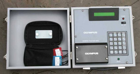
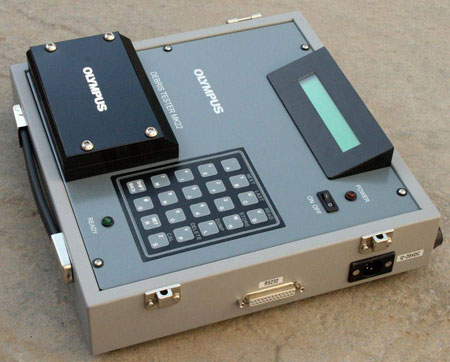
The Olympus Debris Tester™ is a portable instrument used for identifying, evaluating, and recording the presence of magnetic debris found in oil lubricated engines and gearboxes. Examination of engine debris has been established as a means of monitoring engine health, and accurately measuring and recording the amount of debris readings is an essential part of condition monitoring for engines and gearboxes. Among the methods employed is the measurement of the amount of magnetic debris at specific points within the lubrication system.
Theory of Operation
The Olympus Debris Tester MK3 operates on the "unbalanced" AC bridge coil eddy current principle. The measuring head is a very sensitive AC bridge and contains a sensing coil with a balance coil mounted alongside. The bridge is driven by a stabilized, digital 10.5 KHz oscillator. The measurement coil is located beneath the sample slot while the other coil, the balance coil, is built into the measurement head. The measuring head is constructed in such a way as to prevent a sample slide being placed over the balance coil while at the same time maintaining the slide in the correct proximity to the measuring coil.
The magnetic debris collects in filters, sumps and magnetic chip detectors and is then carefully transferred to a test card which is then inserted into the Debris Tester. The components ahead of each collection point in the lubrication system are monitored by plotting the measurement from that point of collection.

When a sample is slid into the instruments reading slot, the bridge becomes unbalanced and circuits within the instrument detect the amount of ferritic content on the slide that is centered over the measuring coil. This reading is then converted by the installed software into a numeric value that is then displayed as a Peak Value on the instrument's LCD screen. At the same time as sensing the peak value the instrument also senses and displays a current value for the area of the sample over the measuring coil at that time. In both instances the numerical value ascribed to the reading is proportional to the amount of ferritic products present within the sample, the higher the number displayed the higher the ferritic content. The obtained values referred to as Debris Test Units (DTU's) and are displayed on the instrument's Liquid Crystal Display (LCD) and can be stored within its internal memory. DTU data can be plotted against running hours on a suitable graph, relative to a specific aircraft for engine, gearbox and A.P.U.
The instrument is powered from the mains supply via an external AC adaptor or directly from an external DC source.
Analysis of Results
In normal operation, it is typical to see a steadily rising quantity of debris coincident with increasing engine hours, due to normal component wear taking place. Plotting this steady wear on a graph gives a defined Quantity/Hours curve which tracks engine and gearbox health. By plotting accurate readings of the quantity of debris on a graph, users can also identify unpredicted wear in components through readings that move away from their expected position on a plotted curve. This is an early warning that allows operators to plan rectification at a convenient time in the scheduled maintenance, or introduce an update on `Engine Hours/Debris Check' routine, thus saving unnecessary cost through unscheduled downtime and secondary damage.
